Speaker Design
Isobaric Speaker Enclosures: Theory, Math and Design Guide
Published October 8, 2026

Isobaric speaker enclosures pair two drivers so one compound driver can achieve a target low-frequency alignment in roughly half the net box volume of a single driver.
An isobaric speaker enclosure, also called compound loading, uses two matched drivers coupled so they behave approximately like one compound driver. The key benefit is not free output; it is the ability to achieve a similar low-frequency alignment with an effective Vas about half that of one driver, which can reduce the required net enclosure volume by about 50 percent for the same modeled alignment. VUE Audiotechnik describes the same half-Vas modeling approach for its isobaric subwoofers.
Short version: Isobaric is a space-saving trade. Two drivers can give you roughly the same modeled bass alignment in half the net box volume, but you pay with a second driver, more enclosure complexity, more weight and, for the usual parallel-wired implementation, about 3 dB lower efficiency per total electrical watt. It is most valuable when enclosure volume is the hard constraint.
What is an isobaric enclosure?
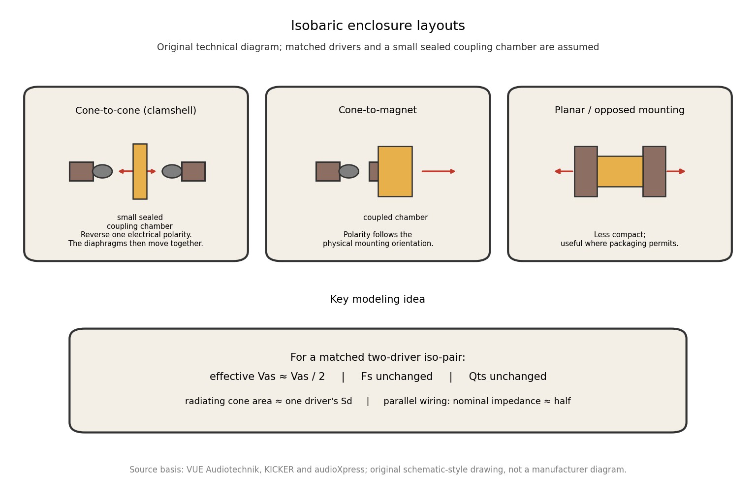
KICKER defines isobaric as “compound loading,” meaning two drivers are coupled to act as one. In the classic arrangement, the drivers share a small sealed chamber between their diaphragms. One driver radiates into the main enclosure or directly to the outside, while the second driver pressurizes the coupling chamber and mechanically couples its motion to the first.
The word isobaric describes the design goal of keeping the pressure difference in the coupling region small enough that the two diaphragms act as a tightly coupled pair. In the ideal model, the pair can be treated as one driver whose effective equivalent compliance volume, Vas, is half the original driver's Vas. VUE's design note explicitly recommends the half-Vas approach for isobaric modeling.
Isobaric terminology and the parameters that matter
| Term | Meaning |
|---|---|
| Isobaric / compound loading | Two coupled drivers acting approximately as one compound driver. |
| Iso-pair | The matched pair of drivers used as the compound unit. |
| Vas | Equivalent air volume having the same compliance as the driver's suspension. |
| Fs | Driver free-air resonant frequency. |
| Qts | Total driver Q at resonance from electrical and mechanical losses. |
| Sd | Effective radiating cone area. |
| Qtc | System Q of a sealed box at its resonance. |
| Coupling chamber | The small sealed air space between the two isobarically coupled diaphragms. |
Vas is especially important because it is the parameter that changes in the simplest compound-driver model. KICKER defines Vas as the air volume having the same compliance as the driver suspension. The other Thiele/Small parameters still need to be entered correctly into whatever modeling software you use.
What changes when two drivers become one iso-pair?
Vas is approximately halved
For two matched drivers operating as an ideal coupled pair, the equivalent compliance is halved, so the effective Vas becomes approximately Vas_pair = Vas_single / 2. That is the mathematical reason the box can be half the required net volume for a comparable alignment. VUE states the same rule directly.
Fs remains approximately unchanged
The combined pair has roughly twice the moving mass, but its effective compliance is roughly half. Because the resonant frequency depends on the product of moving mass and compliance, the two changes cancel in the ideal model and Fs remains approximately unchanged.
Qts remains approximately unchanged in the simple model
For a matched pair, the standard compound-driver model treats Qts as unchanged while Vas changes. That lets you take the original driver's Fs, Qts and other appropriate parameters and model the pair by entering the reduced Vas. The real system can deviate because the two drivers are not perfectly identical and because the coupling chamber has finite acoustic volume.
Radiating cone area does not become two times larger
This is one of the most common misunderstandings. In a classic isobaric arrangement, only one cone directly radiates into the main acoustic load. The inner driver's motion is coupled through the trapped air chamber. You therefore do not get the same direct-radiating cone-area benefit as simply putting two woofers on the front baffle.
Electrical load changes
With two identical nominal-4-ohm drivers wired in parallel, the nominal load becomes about 2 ohms. In series it becomes about 8 ohms. VUE notes that the drivers in a cone-to-cone implementation must be driven so their acoustic motions are in the required phase, which means the electrical polarity may need to be reversed because the physical mounting is reversed.
The main advantage: smaller required box volume
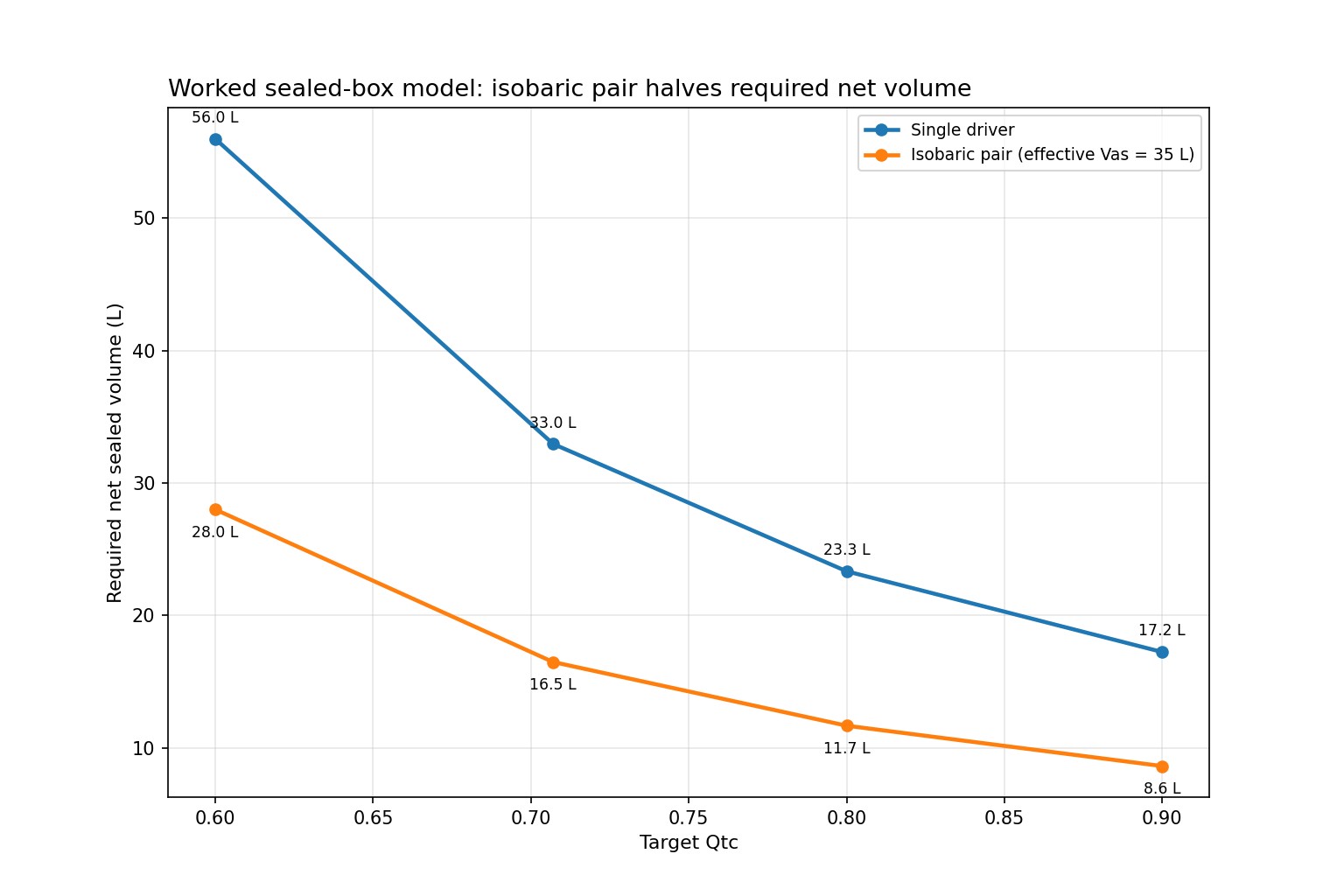
The useful comparison is not “two drivers versus one driver” in the abstract. Compare two designs that target the same frequency response shape. If a single driver requires a sealed net volume based on its 70 L Vas, the matched isobaric pair can be modeled with an effective 35 L Vas and therefore needs roughly half the net box volume for the same target Qtc.
Worked sealed-box example
Consider a hypothetical driver with Vas = 70 L, Qts = 0.40 and Fs = 30 Hz. We will target several sealed-box Qtc values to show exactly what the half-Vas change does. This is a calculated example, not a recommendation for a particular commercial driver.
For a conventional sealed system:
Vb = Vas / ((Qtc / Qts)^2 - 1)
For the isobaric pair, the same equation is used after substituting Vas_pair = 35 L.
| Target Qtc | One driver, net Vb | Isobaric pair, net Vb |
|---|---|---|
| Qtc 0.600 | 56.0 L | 28.0 L |
| Qtc 0.707 | 33.0 L | 16.5 L |
| Qtc 0.800 | 23.3 L | 11.7 L |
| Qtc 0.900 | 17.2 L | 8.6 L |
At the commonly used Qtc = 0.707 target, the single-driver box calculates to 33.0 L, while the isobaric pair calculates to 16.5 L. The response target is the reason the required net volume is halved; the physical cabinet itself is not literally guaranteed to be half the external dimensions because the second driver's structure and the coupling chamber occupy space.
Why isobaric is not a free 3 dB gain
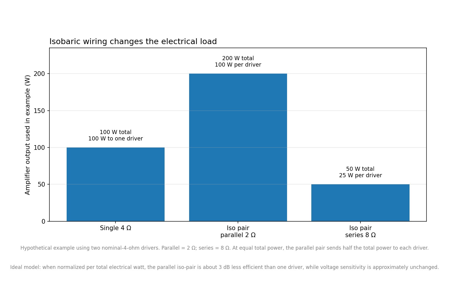
Adding a second driver sounds as though it should automatically increase output. The compound configuration does not work that way. In the ideal parallel-wired model, the pair has approximately the same voltage sensitivity as the original single driver but draws more total power at that same voltage, so the system is about 3 dB less efficient when normalized per total electrical watt. AudioXpress describes the same trade as half the Vas in exchange for a net 3 dB loss in power efficiency.
This is one reason isobaric should be considered a space trade, not a performance loophole. You spend driver count, enclosure complexity and amplifier capacity to buy a smaller acoustic enclosure.
Worked electrical example
Using two hypothetical nominal-4-ohm drivers:
| Configuration | Nominal load | Illustrative amplifier power | Power per driver |
|---|---|---|---|
| One nominal 4 Ω driver | 4 Ω | 100 W | 100 W |
| Two 4 Ω drivers, parallel | 2 Ω | 200 W | 100 W each |
| Two 4 Ω drivers, series | 8 Ω | 50 W | 25 W each |
In parallel, 200 W total into 2 ohms means 100 W per driver. With 50 W total into an 8-ohm series pair, each driver receives 25 W. The exact safe power level in a real build must come from the actual drivers and amplifier, not from this hypothetical example.
Choosing the physical isobaric arrangement
Cone-to-cone or clamshell
For a car-audio subwoofer, cone-to-cone is attractive because it can make the overall assembly compact. The two cones face each other across a small chamber. Because their physical acoustic orientations are reversed, the electrical polarity of one driver is reversed so the diaphragms move together in the coupling chamber. VUE specifically uses cone-to-cone push-pull isobaric loading in its high-output subwoofers.
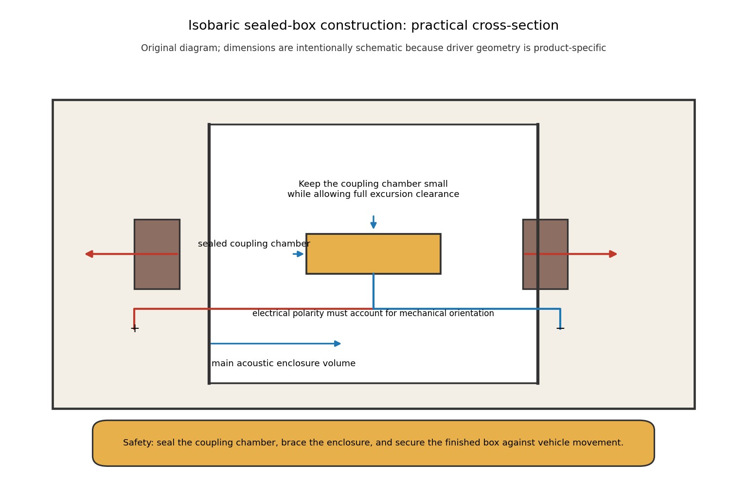
The chamber should be as small as practical without allowing the moving parts to contact one another. VUE emphasizes the same principle: make the coupling region small enough that the diaphragms are tightly coupled.
Cone-to-magnet
Cone-to-magnet arrangements can also work as isobaric pairs. Their main practical advantage is that the driver geometry can be easier to package than a very tight face-to-face clamshell in some constructions. The exact polarity relationship depends on the mechanical orientation, so follow the acoustic movement rather than blindly copying a wiring diagram.
Planar and other opposed layouts
Other layouts can create compound loading, but they are usually less space-efficient than the clamshell approach in a vehicle. The point of the design is not the visual arrangement; it is the tight coupling between the two diaphragms and the ability to model the pair as a compound driver.
Designing the coupling chamber
The coupling chamber is not free “bonus” enclosure volume. It is a small acoustic element whose compliance can become important when the chamber is too large. That is why the chamber should be minimized without restricting the moving parts.
There are three practical requirements:
- Enough clearance: cones, surrounds, spiders and frames must never collide through their full operating excursion.
- Airtight construction: leaks defeat the intended sealed coupling behavior and can make the simple model less accurate.
- Rigid structure: the driver mounting surfaces should not flex under the reaction forces from two coupled motors.
Do not build the chamber by simply sandwiching two baffles together and assuming every driver pair will fit. Frame depth, magnet diameter, surround clearance, basket openings and service access all need to be checked from the actual driver drawings.
How to model an isobaric sealed enclosure
- Collect the actual driver's Fs, Qts and Vas, plus the other parameters needed by your modeling software.
- Create the compound pair using the software's isobaric/compound option when available, or manually substitute Vas/2 in the basic ideal model.
- Choose the target alignment, such as a desired Qtc, and calculate the resulting net volume.
- Check the resulting cone excursion and amplifier load. The smaller box does not remove excursion limits.
- Add the physical displacement of the drivers, braces, coupling structure and other internal parts when converting the modeled net volume into gross cabinet dimensions.
Software can be very useful here, but the result remains a model. Thiele/Small parameters describe low-frequency small-signal behavior; real high-power performance can change with temperature, excursion, suspension nonlinearity and other effects.
How to design an isobaric vented box
An isobaric pair can also be used in a vented enclosure. The basic modeling step remains the same: treat the pair as a compound driver and use approximately half the single driver's Vas. VUE explicitly describes isobaric modeling as essentially the same as conventional vented-box modeling once the Vas value is divided by two.
Do not assume that a smaller box means a proportionally smaller port. The port still has to achieve the intended tuning frequency while keeping air velocity and turbulence acceptable. The enclosure also needs the correct net volume after subtracting driver, port and brace displacement.
For a car-audio build, model the actual vented alignment rather than using a generic “half-size ported box” rule. Once the port is part of the acoustic system, tuning frequency, port area, port length, and driver excursion below tuning all need to be checked together.
Practical construction workflow
- Choose matched drivers. The simplest and most predictable design uses two identical drivers from the same model and, where practical, similar measured parameters.
- Verify the T/S data. Use the manufacturer's parameters for your exact driver version or measure the drivers if the design is critical.
- Model the compound pair. Use an isobaric setting or half the single driver's Vas for the ideal model.
- Lay out the chamber first. Confirm mechanical clearance at full intended excursion before committing to panel dimensions.
- Build the cabinet rigidly. Use adequate material thickness, bracing and airtight joints.
- Wire the drivers deliberately. Confirm the required acoustic phase from the physical mounting orientation, then verify the final electrical load.
- Secure the enclosure in the vehicle. A heavy enclosure must not be free to move in a collision.
Isobaric versus a conventional dual-driver box
| Alignment | How it works | Main strength | Main limit |
|---|---|---|---|
| Conventional single-driver sealed | One driver, conventional Vas | Lowest parts count; normal efficiency | Needs more net volume when Vas is large |
| Isobaric sealed | Two matched drivers; Vas/2 model | Compact box; simple response modeling | Two drivers, extra depth, lower efficiency per total watt |
| Conventional dual-driver sealed | Two direct-radiating drivers | More cone area and potential output | Box volume generally scales with the combined system |
| Isobaric vented | Two matched drivers; half-Vas model plus vent | Compact vented implementation | Port design, chamber construction and low-frequency protection still matter |
A conventional dual-driver box makes direct use of both cones, which can increase output capability when the cabinet is large enough. Isobaric gives up that direct-radiating cone-area advantage to obtain the half-Vas volume benefit. That is why isobaric is most compelling when the enclosure must be unusually small.
When isobaric makes sense in a car?
The classic reason is simple: you have enough driver hardware and amplifier capacity but not enough enclosure space. Historical car-audio builds used push-pull isobaric loading specifically to solve packaging problems in constrained vehicles.
Modern car subwoofers often have smaller Vas values, so the benefit may be less dramatic. If a single modern woofer already reaches the required alignment in the space you have, a conventional single-driver or dual-driver design may deliver a better cost-to-output result.
Advantages and limitations
Strengths
- Smaller modeled net enclosure: effective Vas is approximately halved for a matched pair.
- Flexible compound-driver engineering: two drivers can create a mechanical package with parameters that may be difficult to obtain from one driver.
- Potential push-pull distortion benefit: opposing mechanical orientation can cancel some suspension nonlinearities when the drivers are well matched. VUE describes this as an additional benefit of its cone-to-cone design.
- Useful for tight automotive packaging: the smaller net acoustic enclosure can be valuable in trunks, spare-wheel wells and other restricted areas.
Limits
- Twice the driver hardware: two motors, two suspensions and more structure are required for roughly one driver's radiating cone area.
- Lower efficiency per total watt: ideal parallel-wired isobaric operation carries about a 3 dB efficiency penalty versus one driver when normalized by total electrical power.
- More depth and construction complexity: the second driver and coupling structure consume physical space that the ideal half-Vas calculation does not remove.
- Mismatch sensitivity: two drivers with meaningfully different parameters weaken the assumptions behind the simple compound model.
- Thermal asymmetry: one driver may experience a different cooling environment from the other, especially in a tight or enclosed inner chamber.
Common mistakes
- Putting the full single-driver Vas into the isobaric simulation: the basic compound model uses half Vas.
- Expecting twice the direct cone area: the inner cone is not normally radiating into the main acoustic space.
- Making the coupling chamber huge: this weakens the tightly coupled assumption and consumes physical volume.
- Ignoring final impedance: two nominal-4-ohm drivers in parallel present about 2 ohms before frequency-dependent impedance effects.
- Using random polarity: the electrical polarity must be selected to make the physically reversed drivers move in the required acoustic phase.
- Forgetting net versus gross volume: driver, port and brace displacement must be accounted for.
- Assuming lower box volume means higher output: the design trades volume for efficiency, hardware and power rather than creating free performance.
Safety and installation
A finished subwoofer enclosure is heavy and can become a projectile in a collision. Secure it to the vehicle using an attachment method appropriate for the vehicle structure and enclosure mass. Electrical wiring should be fused correctly, protected from abrasion and kept clear of moving or hot components. Do not work on powered wiring, and observe hearing-safety precautions when testing high-output systems.
Isobaric design checklist
- Two matched drivers with compatible T/S parameters.
- Effective
Vas = Vas_single / 2in the ideal compound model. - Correct polarity for the chosen physical orientation.
- Small sealed coupling chamber with full excursion clearance.
- Modeled net volume verified after all internal displacement is accounted for.
- Amplifier load checked for the actual wiring configuration.
- Excursion, tuning and port velocity checked for vented alignments.
- Finished enclosure rigidly secured in the vehicle.
Sources and further reading
- VUE Audiotechnik — Isobaric Subwoofer Design
- KICKER — Glossary: Isobaric, Vas, Qts, Fs, impedance and SPL terminology
- audioXpress — Patent Review: Loudspeaker Apparatus
- Parts Express — loudspeaker and enclosure design resources
Last reviewed: October 2026
Isobaric Speaker Enclosures FAQ
What is an isobaric speaker enclosure?
An isobaric enclosure couples two matched drivers so they behave approximately as one compound driver. The main design benefit is an effective Vas of about half the single driver's Vas, which can deliver a similar low-frequency alignment in roughly half the net enclosure volume.
Does an isobaric pair double bass output?
Not automatically. In the ideal matched-pair model, the pair has about the same radiating cone area as one driver because only one outer cone directly radiates, while the second driver pressurizes the coupling chamber.
Does isobaric change Fs or Qts?
For the ideal matched-driver compound model, Fs and Qts are treated as unchanged while Vas is halved. The physical reason is that the combined moving mass doubles while the combined compliance is halved.
How small should the chamber between isobaric drivers be?
The coupling chamber should be kept as small as practical while still allowing the drivers to move freely without mechanical contact. A large chamber adds acoustic compliance and makes the simple Vas/2 model less representative.
Do isobaric subwoofers need twice the amplifier power?
A matched pair usually requires more total amplifier power than one driver for the same voltage-normalized acoustic result. With two nominally 4-ohm drivers wired in parallel, the load becomes about 2 ohms and the pair has about 3 dB lower efficiency when sensitivity is normalized per total electrical watt.
Can isobaric be used with a ported box?
Yes. The same compound-driver idea can be modeled in a vented enclosure using the effective half Vas of the pair. The port still has to be designed for the resulting enclosure, tuning, air velocity and effective radiating system.
Is isobaric still useful with modern subwoofers?
It can be, especially when physical depth or enclosure volume is the dominant constraint. Many modern subwoofers have smaller Vas values than some historical car-audio drivers, so the space savings may no longer justify the cost, weight, heat and amplifier requirements in every project.
Can any two woofers be used as an isobaric pair?
The cleanest textbook implementation uses matched, identical drivers with similar Thiele/Small parameters. Mixing drivers can be engineered, but the simple Vas/2 model becomes less reliable and the coupling chamber can expose differences in compliance, excursion and motor behavior.